
Overview of EE Architecture
Electrical/Electronic (EE) architecture in electric vehicles defines how electronic control units (ECUs), sensors, actuators, and communication networks are organized and integrated to manage increasingly complex vehicle systems. Modern EE architectures address the challenges of autonomous driving, high-voltage power management, and over-the-air updates while maintaining functional safety compliance.
Primary Architecture Topologies
Distributed Architecture
The traditional distributed architecture organizes the vehicle around multiple individual Electronic Control Units (ECUs), each responsible for a specific function. In this approach, the powertrain domain manages engine and transmission control, the body domain handles lighting and comfort functions, and the infotainment domain manages entertainment and navigation systems. While proven in conventional vehicles, this architecture becomes increasingly complex in EVs, with some models containing as many as 150 ECUs. This multiplicity increases wiring harness length, weight, cost, and potential points of failure.
Domain-Oriented Architecture
Domain controllers consolidate related ECUs into five primary domains: connectivity/telematics, automated driving and ADAS, powertrain and vehicle dynamics, body and comfort, and in-vehicle experience/infotainment. Each domain controller manages its specific functional area while communicating with other domains through a central bus system. This intermediate approach reduces the complexity of a fully distributed system while maintaining some functional separation, making it easier to implement domain-specific safety strategies.
Zonal Architecture
Zonal architecture divides the vehicle into physical zones—such as front-left, front-right, rear-left, rear-right, and center—with each zone managed by a dedicated Zone Control Unit (ZCU). Rather than organizing by function, all electrical components within a zone are connected to the local zone controller, which acts as a communication gateway. This architecture offers significant advantages in modern EVs: reduced wiring complexity and weight, improved data transfer rates, support for over-the-air updates, and faster software development cycles. However, latency in communication and automotive cybersecurity represent key implementation challenges.
Centralized/Software-Defined Architecture
The software-defined vehicle (SDV) approach uses one or more powerful central computing platforms to execute cross-domain logic and safety-critical functions. This architecture decouples software from hardware, enabling independent upgrades and OTA updates. Vehicles transition from 70–100+ distributed ECUs to a centralized system with high-performance compute platforms and zonal control modules that aggregate sensor data, actuate loads, and distribute power locally. This approach simplifies the overall electrical architecture while enabling dynamic feature delivery and personalized user experiences.
Hybrid and Modular Architectures
Many modern EVs employ hybrid approaches that combine elements of domain controllers and zonal controllers to optimize specific functions and maintain redundancy. For example, safety-critical systems such as powertrain and chassis might utilize dedicated domain controllers, while body and comfort functions are handled by zonal controllers. This balanced approach allows manufacturers to apply the most appropriate architecture for each vehicle domain’s specific requirements.
EE Architecture Topologies and Safety: Visual Guide
EE Architecture Types Comparison
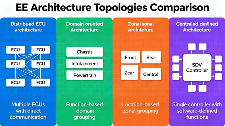
Four primary EE architecture topologies for electric vehicles compared visually
This visualization shows the evolution and comparison of four primary EE architecture approaches used in modern electric vehicles, from traditional distributed systems to cutting-edge centralized software-defined architectures.
Architecture Topologies in Detail
Distributed Architecture with ECU Locations
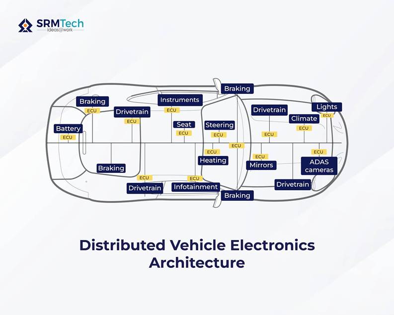
Distributed vehicle electronics architecture showing locations of electronic control units (ECUs) within various systems of a car.
This diagram illustrates the traditional distributed approach where Electronic Control Units are physically dispersed throughout the vehicle, each managing specific functions like braking, drivetrain, battery management, climate control, and infotainment. The scattered placement of ECUs throughout the vehicle increases wiring complexity but provides fault isolation.
Domain-Oriented and Zonal Architecture Comparison
Comparison of distributed, domain, and zonal E/E architectures in vehicles showing ECU arrangements and data exchange pathways.
This comprehensive technical illustration compares three major architecture approaches side by side. The left section shows distributed architecture with individual function-specific ECUs. The middle demonstrates domain architecture where controllers manage all vehicle domains (perception, infotainment, powertrain, body, chassis). The right section shows zonal architecture with Zone Control Units managing specific physical regions of the vehicle, supported by high-performance computing units for demanding tasks.
Domain Controller Architecture
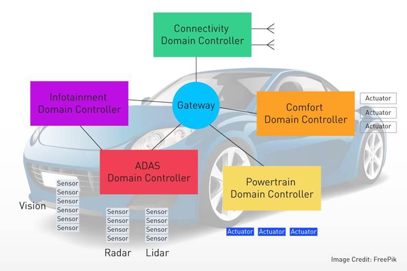
A conceptual diagram of vehicle electronics architecture showing multiple domain controllers connected through a gateway and associated sensors and actuators in an electric vehicle.
This diagram depicts the domain controller approach where the vehicle’s electronics are organized around five primary domains: connectivity (green), infotainment (purple), ADAS (red), comfort (orange), and powertrain (yellow). All domains connect through a central gateway that coordinates communication, sensor data, and actuator commands. Sensors including vision, radar, and lidar feed information to the ADAS domain controller.
Safety Architecture and Standards
Automotive Safety Integrity Levels (ASIL)
Comparison of ASIL A and ASIL D levels showing differences in risk severity, exposure, controllability, and development rigor according to ISO 26262.
This comparison table illustrates the four levels of automotive safety defined by ISO 26262 functional safety standards. ASIL A represents minor issues with minimal safety requirements (such as infotainment alerts), while ASIL D encompasses life-threatening failures requiring the highest development rigor (such as emergency braking and steering control). Safety-critical functions in EVs typically require ASIL D classification.
Multi-Layered Safety Architecture
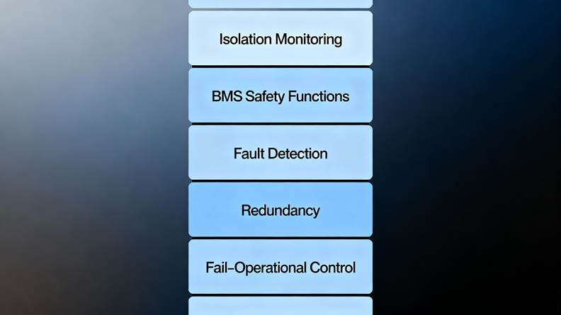
Multi-layered safety architecture in EV electrical systems
This diagram represents the comprehensive safety framework in EV electrical systems, showing how multiple safety layers work together: isolation monitoring constantly checks insulation between voltage domains, the BMS monitors battery health and prevents thermal runaway, fault detection systems identify anomalies, redundancy mechanisms provide backup functions, and fail-operational control enables degraded operation following failures.
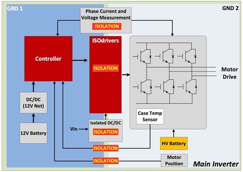
Galvanic Isolation for High-Voltage Safety
Block diagram showing galvanic isolation points in an EV’s high-voltage battery and motor drive system to enhance safety and reliability.
This block diagram illustrates how galvanic isolation protects the low-voltage control circuits from high-voltage motor drive systems. The diagram shows separation between GND1 and GND2 domains, with isolation barriers (marked as “ISOLATION”) between the high-voltage battery and inverter circuits, the controller and motor drive, and measurement sensors. This isolation prevents dangerous current paths while allowing safe data and power transfer.
Fail-Operational Safety Systems
Fail-Operational Architecture for Automated Driving
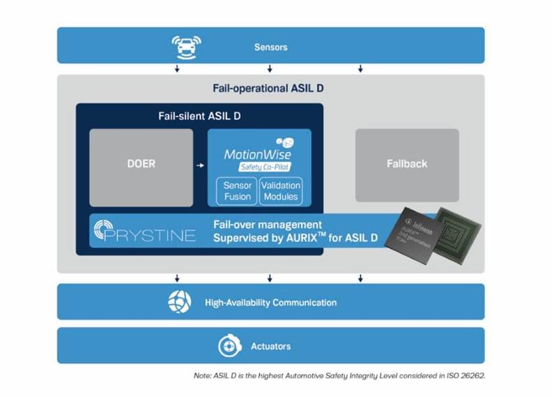
Fail-operational ASIL D architecture for vehicle control showing sensors, fail-silent components, fallback, fail-over management, communication, and actuators.
This diagram shows a fail-operational ASIL D architecture used in highly automated driving vehicles. The system includes redundant processing paths, with a primary fail-silent ASIL D block containing sensor fusion and validation modules, plus a fallback system. The AURIX processor supervises fail-over management, ensuring the vehicle can maintain safe operation and navigate to a safe state even if primary systems fail. High-availability communication connects to actuators for continuous control authority.
Fail-Operational Software Architecture in AUTOSAR
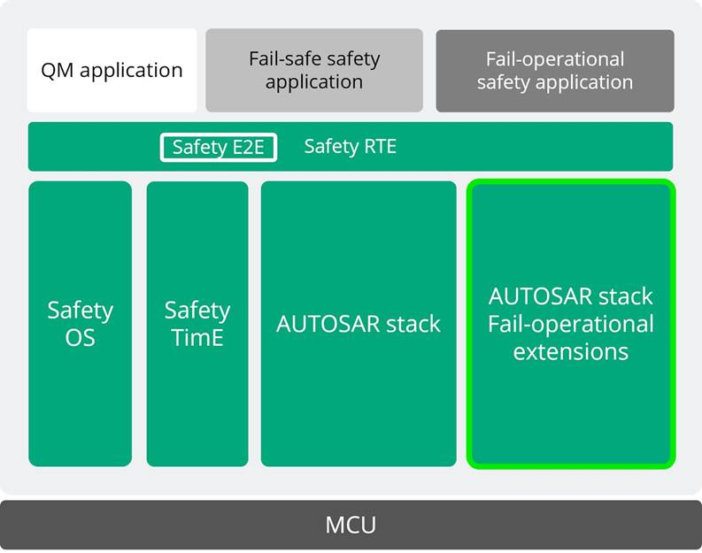
Fail-operational safety architecture layers in an AUTOSAR-based vehicle control system illustrating the AUTOSAR stack and fail-operational extensions.
This layered diagram illustrates how fail-operational safety is implemented within the AUTOSAR software stack. The foundation is the microcontroller unit (MCU), above which run the Safety OS, Safety Time, and AUTOSAR stack with fail-operational extensions. Applications are segregated into three types: quality-managed (QM) applications, fail-safe safety applications, and fail-operational safety applications. Safety E2E (End-to-End) and Safety RTE (Runtime Environment) components ensure message integrity and timing across the architecture.
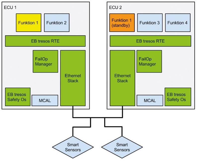
Redundant ECU Architecture with Failover
Fail-operational safety architecture with dual ECUs and smart sensors illustrating redundancy and failover in vehicle control.
This detailed architectural diagram shows how fail-operational safety works across two Electronic Control Units. ECU 1 actively runs Function 1 and Function 2, while ECU 2 operates Function 1 in standby mode along with Function 3 and Function 4. Both ECUs connect to smart sensors and communicate via an Ethernet stack. The FailOp Manager in each ECU monitors system health and orchestrates failover when needed, ensuring uninterrupted control of critical functions.
Communication Protocol Considerations
FlexRay Communication Protocol
FlexRay communication protocol in automotive showing ECU interaction and scheduling methods like Round Robin, Fixed Priority, and EDF.
This diagram illustrates how the FlexRay communication protocol processes events within multiple Electronic Control Units connected to a shared bus. Three scheduling strategies are shown—Round Robin, Fixed Priority, and Earliest Deadline First (EDF)—each determining how messages are prioritized and transmitted. Input events are processed according to the selected strategy, producing predictable, deterministic output events with minimal latency, making FlexRay ideal for safety-critical real-time control.
Key Takeaways from Visual Analysis
Modern EV EE architectures employ sophisticated combinations of topology types optimized for their specific requirements. Safety-critical functions increasingly utilize distributed redundancy with fail-operational capability, allowing vehicles to detect failures, execute fallback strategies, and maintain operation until reaching safe states. Communication protocols are carefully selected based on requirements—LIN for non-critical functions, CAN for general ECU communication, FlexRay for real-time safety-critical functions, and Automotive Ethernet for high-bandwidth applications like autonomous driving perception.
High-voltage safety depends on multiple protective layers: galvanic isolation between voltage domains, continuous isolation monitoring to detect insulation degradation, comprehensive BMS functions including thermal management, and redundant sensor and processor architectures. ISO 26262 functional safety standards provide the framework ensuring all safety-critical components meet appropriate ASIL levels through rigorous development, verification, and validation processes. These visual representations demonstrate how modern EVs integrate complex electrical architectures with multiple safety mechanisms to provide robust, reliable, and safe operation even during component failures.
Communication Protocols and Network Infrastructure
EE architectures depend on multiple communication protocols optimized for different requirements:
LIN (Local Interconnect Network)
LIN is a single-wire serial protocol suitable for low-speed, non-critical applications with maximum data rates of 20 kbps. It reduces implementation cost and complexity for functions like window controls and seat adjustments.
CAN (Controller Area Network)
CAN operates at up to 1 Mbps and supports robust peer-to-peer communication where any node can initiate messages. Unlike LIN, the failure of one node does not compromise the entire bus, making it suitable for general ECU communication. CAN includes strong error-checking mechanisms and is widely used for battery management system internal communication.
FlexRay
FlexRay is a high-speed, deterministic, fault-tolerant protocol designed specifically for safety-critical applications. Supporting data rates up to 10 Mbps, FlexRay uses time-triggered communication with dual-channel redundancy to ensure predictable, reliable message delivery for functions such as advanced driver assistance systems, electronic stability control, and active suspension. Its synchronized communication ensures low jitter, making it ideal for real-time control loops where timing precision is critical.
Automotive Ethernet
Modern EVs increasingly employ high-speed Automotive Ethernet for inter-zone and inter-domain communication, providing significantly greater bandwidth than CAN or FlexRay. Ethernet enables rapid data transfer for compute-intensive tasks like autonomous driving perception and centralized software platforms.
Safety Considerations in EE Architecture
Functional Safety Standards
Electrical and electronic systems in EVs must comply with ISO 26262, the international standard for road vehicle functional safety. ISO 26262 structures safety requirements around a V-model development process, emphasizing bidirectional traceability between development phases. The standard introduces Automotive Safety Integrity Levels (ASILs), categorizing risk into four levels from A (least risky) to D (highest risky) based on severity, exposure, and controllability of potential failures.
Redundancy and Fault Tolerance
Modern EV architectures implement multi-layered redundancy to ensure continued operation during component failures. This includes hardware redundancy through dual sensors or parallel processing paths, software redundancy through independent algorithms monitoring each other, and communication redundancy via dual-channel networks like FlexRay. For example, safety-critical power converters can employ redundant ECU architectures where a primary controller operates in active mode while a backup operates in passive standby, continuously monitoring the primary and assuming control upon fault detection.
Fail-Operational Capability
Modern EVs, particularly those with autonomous capabilities, increasingly employ fail-operational architectures that maintain degraded but continuous operation following failures. Rather than immediately halting (fail-safe), fail-operational systems detect failures, trigger fallback strategies, and maintain functionality until reaching a safe state. For instance, if a positioning sensor fails, the system can switch to dead-reckoning using odometer and steering wheel inputs to navigate to a safe parking location. This approach enhances passenger safety, reduces traffic disruption, and mitigates risks to pedestrians.
High-Voltage System Protection
EV electrical architectures incorporate multiple protection mechanisms for high-voltage systems. Galvanic isolation, typically semiconductor-based, prevents current flow between different voltage domains while allowing data and power transfer. This protects both equipment and occupants from electrical hazards. Additionally, reinforced isolation provides two levels of protection against electrical shock through greater distance across the isolation barrier, with 100% safety testing at 5 kVac RMS and minimum creepage distances of 6.4 mm.
Isolation Monitoring
Isolation monitoring systems continuously check the insulation quality between high-voltage and low-voltage systems, targeting maintenance of at least 500 Ohms per Volt (500 Ω/V) according to Federal Motor Vehicle Safety Standard (FMVSS) 305. For a 300V system, this translates to minimum resistance of 150 kilohms. Modern systems often set detection thresholds higher to ensure chassis currents never reach dangerous levels. Isolation monitors provide early warning of problems such as coolant leaks causing short circuits before they escalate into safety hazards.
Battery Management System Safety
The Battery Management System (BMS) serves as the central safety guardian for the high-voltage battery pack. The BMS performs continuous monitoring of voltage, current, temperature, and state of charge across all battery cells. Critical BMS protection mechanisms include overcharge prevention, overdischarge protection, overtemperature management, overcurrent limiting, and short-circuit detection. The BMS also monitors state of health (SOH) to provide early warnings of potential battery issues. Thermal management represents a particularly critical function, as the BMS prevents thermal runaway—an uncontrollable temperature spike that could result in fire or explosion—by continuously monitoring cell temperatures and deploying cooling strategies as needed. The BMS communicates with the onboard charger to modulate charging rates, maintaining safe operating conditions throughout the charging process.
Hazard Analysis and Risk Assessment
ISO 26262 mandates rigorous Hazard Analysis and Risk Assessment (HARA) processes for EV-specific systems like battery management. This systematic approach identifies potential hazards and assesses their risks, guiding implementation of necessary safety measures. Safety goals are defined based on risk assessment results, with verification and validation processes confirming achievement of these goals.
Requirements Traceability and Configuration Control
Functional safety requires that all safety requirements remain traceable throughout the vehicle’s entire lifecycle, from concept through decommissioning. Configuration control ensures that changes to any safety-related component are properly documented, assessed for impact on other systems, and validated before implementation. This formal process prevents unintended consequences from engineering changes.
Practical Design Trade-offs
The choice of EE architecture involves several important trade-offs. Fully centralized architectures offer maximum software flexibility and cost optimization but present challenges with real-time control loop latencies and single-point-of-failure risks if communication links fail. Distributed approaches maintain some application software in zone or domain controllers, requiring more complex integration but offering better fault isolation. Most modern EVs adopt hybrid approaches tailored to their specific requirements, with safety-critical functions utilizing domain controllers or zonal controllers with robust redundancy, while compute-intensive functions like autonomous driving utilize dedicated central computing platforms.
Software Architecture Frameworks
Modern EE architectures rely on standardized software frameworks such as AUTOSAR (AUTomotive Open System ARchitecture) to ensure interoperability, safety, and modularity. AUTOSAR Classic supports traditional distributed ECU systems, while AUTOSAR Adaptive enables sophisticated centralized and zonal architectures. These frameworks facilitate safety certification according to ISO 26262 requirements and support scalable, modular system development.
Summary
Effective EE architecture design for modern EVs requires careful balance among multiple competing demands: maximizing computational capability while minimizing latency, implementing robust redundancy while controlling cost and complexity, centralizing software control while maintaining safety margins, and enabling rapid feature development through OTA updates while preserving system integrity. Contemporary best practices favor hybrid zonal architectures that consolidate related functions within physical vehicle zones while maintaining dedicated central computing for ADAS and autonomous driving functions, supporting high-speed Ethernet communication, and implementing multi-layered functional safety strategies compliant with ISO 26262 requirements. This approach enables the scalability, flexibility, and safety necessary for next-generation electric and autonomous vehicles.